.png)


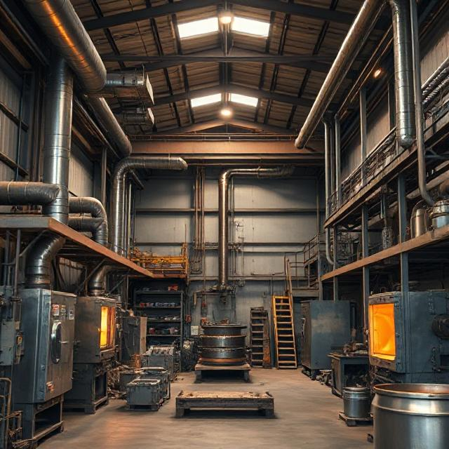


Foundry Facilities
Our foundry facilities are equipped with modern technology, precision-driven machinery, and streamlined processes to ensure the production of high-quality, durable, and performance-driven components that meet the most demanding industry standards with efficiency and consistency.

Foundry Facilities

Foundry Facilities

Foundry Facilities
-
Processing Method
Hand moulding in the foundry industry is a traditional method of creating sand molds for metal casting. Here's a brief overview of the process:
- Pattern Making: A pattern, which is a replica of the final casting, is created using materials like wood, metal, or plastic1.
- Mould Box Preparation: A mould box (flask) is prepared, and the pattern is placed inside it.
- Sand Placement: Sand is carefully packed around the pattern in the mould box. Different types of sand, such as green sand or dry sand, can be used depending on the requirements1.
- Pattern Removal: The pattern is carefully removed, leaving a cavity in the sand that matches the shape of the final casting.
- Core Placement
• Cores: If the casting requires internal features (like holes or cavities), cores are used. Cores are made from sand and are placed into the mould cavity.
• Core Prints: The pattern is designed with core prints, which are recesses that locate and support the cores in the mould. - Pouring
• Gating System: A system of channels is created to direct the molten metal into the mould. This includes:
Sprue: The vertical channel through which molten metal is poured.
Runners: Horizontal channels that distribute the molten metal.
Gates: Entrances to the mould cavity.
• Pouring: The molten metal is poured into the sprue and flows through the gating system into the mould cavity. - Solidification
• Cooling: The metal cools and solidifies inside the sand mould. The cooling rate can be controlled to affect the microstructure and mechanical properties of the casting. - Mould Breakage
• Shakeout: After solidification, the sand mould is broken apart to reveal the casting. This can be done manually or using vibrating equipment.
• Sand Reclamation: The sand from the broken mould can often be reclaimed and reused for future moulds. - Cleaning and Finishing
• Removal of Excess Material: Any excess metal (such as the sprue and runners) is removed from the casting.
• Surface Cleaning: The casting is cleaned to remove any sand or scale that may be adhering to its surface. This can be done using methods like shot blasting or grinding.
• Inspection: The casting is inspected for defects and may undergo additional finishing processes like machining, heat treatment, or surface treatment.
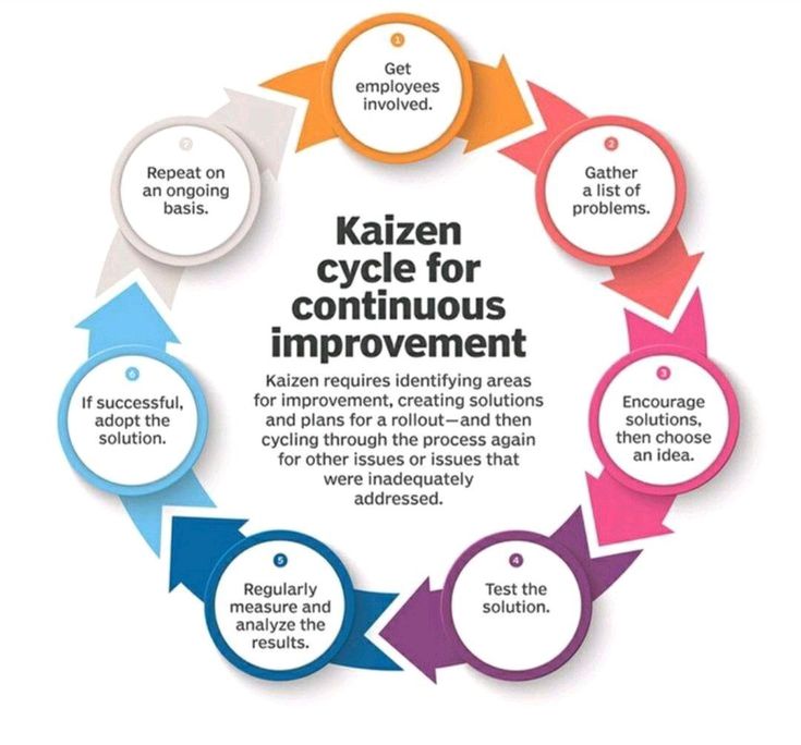
Innovative Production
Our innovative production facility is designed to uphold the highest standards of quality, efficiency, and precision. By integrating advanced technology with streamlined processes, we ensure superior craftsmanship in every component we manufacture. Our commitment to continuous improvement and innovation drives us to exceed industry expectations and deliver exceptional results.
-
 2000 MT
Annual Production Capacity
-
 100 %
100 %Machined Castings
-
 50 +
50 +Employee Strength
-
 54 +
54 +Years of experince
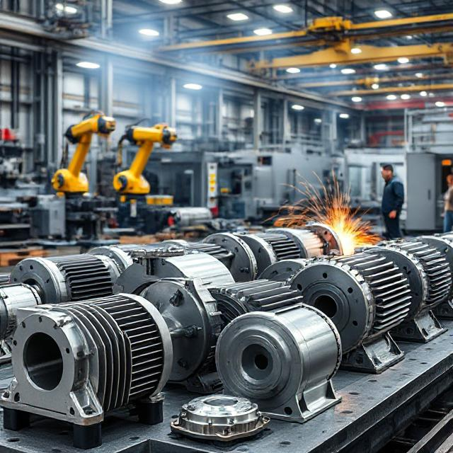
Machining Facilities
Machining is celebrated for its precision and versatility, making it an indispensable process in the manufacturing industry. It allows for the creation of complex geometries and the achievement of tight tolerances, crucial for various engineering applications.
Machining Facilities
Machining Facilities
Machining Facilities
-
Machining Process
Machining is a fundamental manufacturing process in the engineering industry, primarily used for shaping and finishing metal or other materials to achieve precise dimensions and surface finishes. Here's an in-depth look at the machining process and its key components:
- Design And Planning
• Engineering Drawings: Detailed technical drawings specify the dimensions, tolerances, and surface finishes required for the final part.
• Material Selection: The choice of material for the workpiece is based on the design requirements and the intended application of the part. - Setup
• Workpiece Preparation: The raw material is cut to an approximate size using sawing or shearing.
• Machine Setup: The workpiece is securely clamped onto the machine, and the appropriate cutting tools are installed. Common machines used include lathes, milling machines, and drill presses. - Machining Operations
• Turning: A lathe rotates the workpiece while a cutting tool removes material to create cylindrical shapes.
• Milling: A milling machine uses rotating cutting tools to remove material and create flat or contoured surfaces.
• Drilling: Drill bits create holes in the workpiece. Drilling can be performed on a lathe, milling machine, or drill press.
• Boring: Enlarges existing holes to precise diameters.
• Grinding: An abrasive wheel is used to achieve fine surface finishes and precise dimensions. - Cutting Parameters
• Speed: The rotational speed of the cutting tool or workpiece.
• Feed: The rate at which the cutting tool advances into the workpiece.
• Depth of Cut: The amount of material removed in a single pass of the cutting tool. - Coolant Application
• Purpose: Coolants or cutting fluids reduce heat, lubricate the tool, and remove chips from the cutting zone.
• Methods: Coolants can be applied through flood cooling, mist cooling, or direct tool cooling. - Monitoring And Control
• Precision Measurement: Regular measurement and inspection using calipers, micrometers, and other precision tools ensure the workpiece meets specifications.
• Tool Wear Monitoring: The condition of cutting tools is monitored and tools are replaced when worn to maintain quality and efficiency.
- Finishing Operations
• Deburring: Removal of sharp edges or burrs from the workpiece.
• Polishing: Achieving the desired surface finish through polishing or buffing.
• Heat Treatment: Some parts may undergo heat treatment to enhance mechanical properties like hardness and strength. - Quality Control
• Inspection: The final part undergoes thorough inspection to ensure it meets all specifications and quality standards.
• Documentation: All relevant measurements and inspection results are recorded for quality assurance and traceability. - Packaging And Delivery
• Cleaning: The part is cleaned to remove any remaining coolant, chips, or contaminants.
• Packaging: The finished part is packaged appropriately to protect it during storage and transportation.
• Delivery: The part is delivered to the customer or the next stage of the manufacturing process.
- Design And Planning
Laboratory
A well-equipped foundry laboratory ensures that all aspects of the casting process are monitored and controlled, leading to high-quality products and efficient production processes.
Lab Facilities
Lab Facilities
Lab Facilities
-
Laboratory Testing
A laboratory for the foundry industry plays a crucial role in ensuring the quality and integrity of metal castings. Here's an overview of what such a laboratory typically involves:
- Metal Testing
• Purpose: To analyze the composition and properties of the metals used in casting.
• Tests: Chemical analysis, mechanical testing (tensile, hardness, impact tests), and microstructural analysis. - Mould And Core Testing
• Purpose: To verify the quality and integrity of moulds and cores used in casting.
• Tests: Permeability, strength, and dimensional accuracy tests. - Dimensional Inspection
• Purpose: To verify that castings meet dimensional specifications.
• Tools: Calipers, micrometers, coordinate measuring machines (CMM), and other precision measurement tools. - Surface Finish Testing
• Purpose: To ensure the surface finish of castings meets the required standards.
• Tests: : Roughness measurement using profilometers or other surface finish testers. - Environmental Testing
• Purpose: To ensure that castings can withstand environmental conditions they will be exposed to.
• Tests: Corrosion testing, salt spray testing, and exposure to various environmental conditions. - Quality Control Documentation
• Purpose: To maintain records of all tests and inspections for quality assurance and traceability.
• Documentation: Detailed reports, certificates of compliance, and inspection records. - Research And Development
• Purpose: To develop new materials, processes, and technologies for foundry applications.
• Activities: Experimental casting trials, material testing, and process optimization.
- Metal Testing
Measuring & Testing Facility
Our measuring and inspection facilities are designed to ensure accuracy and precision at every stage of production. Using advanced equipment and meticulous quality checks, we validate dimensions, tolerances, and performance standards to guarantee consistency, reliability, and compliance with industry specifications. Every component undergoes rigorous assessment to meet the highest quality benchmarks.
Cylinder Bore Guage
Vernier Caliper

Surface Plate 2x2 ft
